

A Haldex fault shown as a blink sequence or a numeric DTC points straight to one of five areas: wheel sensors, valves, the pump, low voltage, or the ECU itself. Count the flashes, or plug in a scan tool and read the stored code, before you touch a spanner. Everything else in this guide, the blink chart, the component tests, the clearing procedure, builds from that one reading.
TL;DR:
- Counting blink counts and understanding fault codes helps identify whether a Haldex system issue is caused by sensors, valves, the pump, low voltage, or the ECU.
- Diagnostic modes require specific sequences of ignition and button presses, with wheel spin tests needed to accurately diagnose sensor faults.
- Common mistakes include neglecting to verify dual power feeds and miswiring the ABS lamp’s earth connection, which can cause misdiagnosis.
- Proper testing involves measuring electrical resistance, conducting audible click tests, and inspecting wiring before component replacement.
- Accurate fault diagnosis hinges on verifying electrical supply, matching OEM parts to the correct generation, and performing adaptations after pump or controller replacements.
Table of Contents
- Blink counts and numeric codes: a quick reference
- How to enter diagnostic modes and read blink codes correctly
- Common Haldex codes and what they usually indicate
- An ordered workflow to diagnose any displayed code
- Bench and wiring tests that confirm the real fault
- Clearing stored codes and confirming the repair actually worked
- When to repair, adapt, or replace: guidance from Haldexparts
- What technicians consistently get wrong with Haldex faults
- Where to buy OEM Haldex pumps and service kits
- Sources
Blink counts and numeric codes: a quick reference
Haldex controllers on Generation 4 and Generation 5 systems talk to you through the dashboard ABS lamp long before any scan tool gets connected. In simple mode (Mode 1), the lamp flashes a repeating count that maps to a fault group. Learn this table and you can narrow a fault to pump, valve, sensor, or wiring before you’ve even opened the boot.
The flash counts follow a consistent pattern across most Haldex generations, as documented in the blink-code diagnostics sheet:
| Flash count | Fault area | Typical cause |
|---|---|---|
| 1–6 | Wheel speed sensors (positions 1A through 3B) | Open circuit, short, corroded connector, damaged tone ring |
| 7 | Valve group (often solenoid 1) | Coil failure, contamination, stuck plunger |
| 8–9 | Additional valve/solenoid faults | Wiring fault, seized valve, contaminated oil |
| 10 | Low system voltage | Weak battery, poor earth, fuse or relay fault |
| 11 | ECU/controller failure | Internal memory fault, EEPROM corruption |
Numeric DTCs work differently once you’re past the simple chart. In active mode (Mode 2), the same ABS lamp displays a sequence of long and short flashes that spell out a genuine diagnostic trouble code, the kind you’d see on a scan tool as something like C1112 or a five-digit internal fault reference. The Haldex service manual documents this display method and confirms the controller can present up to nine stored faults in a single active-mode sequence, cycling through each one before repeating from the start as covered in the installation/service manual.
That nine-fault ceiling matters more than it sounds. On a vehicle with a genuinely tired system, you might be watching flash five of nine and mistake it for the whole story. If the lamp keeps cycling past a fault you’ve already noted, wait for the full loop to repeat before you conclude you’ve captured everything.
Using the table in the field is straightforward once you know the drill:
- Count the first blink group carefully. A pause of roughly two seconds separates each fault in the sequence.
- Cross-reference the count against the table above before assuming which component to test.
- If the count sits at 7 through 9, treat it as a valve-group issue and check coil resistance before ordering parts.
- Never diagnose from a single blink count alone if the vehicle has known history. Cross-check stored codes too.
A count of 10 or 11 changes your entire approach. Instead of grabbing a multimeter for a sensor, you’re now looking at the electrical supply or, if worse, the controller’s own memory. Skipping that distinction wastes a lot of diagnostic time on the wrong end of the car.
How to enter diagnostic modes and read blink codes correctly
Haldex controllers on most Generation 4 and Generation 5 systems cycle through four distinct diagnostic modes, and getting the sequence wrong is the single most common reason technicians misread a fault. The modes are Simple (Mode 1), Active (Mode 2), Stored or passive (Mode 3), and Configuration (Mode 4). Each is triggered by a specific pattern of ignition cycling combined with a diagnostic button press or bridge connection, depending on the vehicle platform.
Pro Tip: Write down the exact ignition sequence for the specific Haldex generation you’re working on before you start. Gen 4 and Gen 5 controllers don’t always share the same mode-entry pattern, and guessing costs you a reset and a restart.
Here’s the general sequence that applies across most common platforms:
- Turn the ignition on with the engine off and wait for the ABS lamp to settle into its normal idle state.
- Locate the diagnostic connector or button specified for the vehicle, then follow the manufacturer’s press-and-hold or bridge sequence to enter Mode 1.
- Watch the lamp for the first blink group and record the count against the reference table.
- Cycle the ignition or repeat the button sequence as specified to progress to Mode 2 for active numeric fault display.
- For stored faults from previous drive cycles, switch to Mode 3, which shows faults logged in memory even if they aren’t currently active.
- Use Mode 4 only when you need to check or adjust controller configuration, such as tyre size settings, since this mode does not display faults.
Wheel-speed mode has its own, stricter rule. When you’re isolating a sensor fault, you spin one wheel at a time and read the corresponding flash count. According to the blink-code bulletin, each wheel position has a distinct flash signature (S1A through S3B), and spinning more than one wheel simultaneously produces an ambiguous or missing readout. Jack one corner up, spin the hub by hand, and watch for the matching flash count before moving to the next wheel.
Two mistakes come up constantly in the workshop. The first is wiring the ABS lamp’s earth connection incorrectly during a repair, which leaves the lamp permanently lit or flickering regardless of the actual fault state. The second, and this one catches out experienced technicians too, is a persistent code 07 that reappears even after a sensor looks fine on the bench. Haldex’s own technical guidance addresses this directly: a displayed ‘07’ can coexist with an earlier stored sensor fault, and the fix is often to rotate the affected wheel under permanent power to clear the residual flag according to Haldex TechTopics. If the lamp stays lit despite that, check the wiring continuity to earth at the ECU connector, specifically pin D, before assuming the sensor itself has failed.
Common Haldex codes and what they usually indicate
Every Haldex fault falls into one of four practical buckets: sensors, valves, the pump, or power and controller issues. Knowing which bucket you’re in changes the entire test sequence, so it’s worth separating them clearly rather than chasing symptoms.
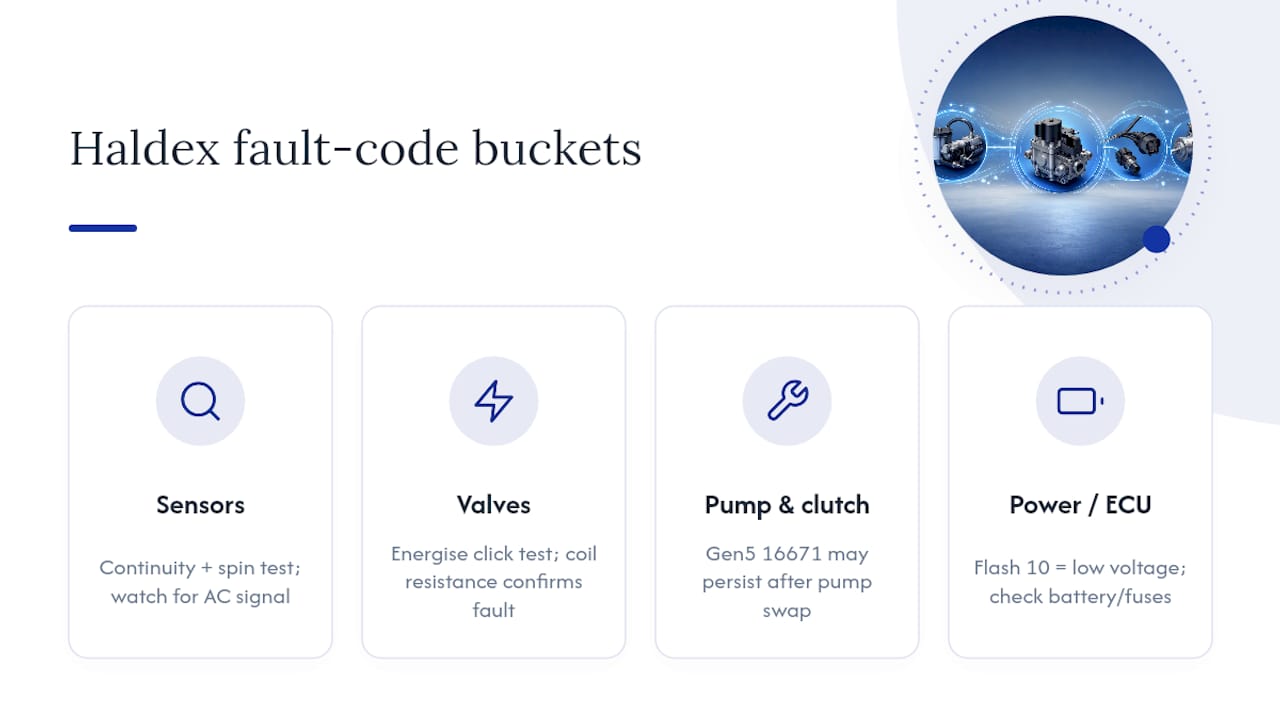
Sensor codes typically show up as opens, shorts, or a weak signal rather than total silence. A wheel sensor reading zero resistance usually means a shorted winding; an infinite reading means an open circuit, often at the connector rather than the sensor coil itself. The quickest field test is a continuity check with the connector disconnected, followed by a spin test: rotate the wheel by hand while watching for a fluctuating AC voltage signal on the sensor output. Corrosion inside the connector is the most common culprit on older vehicles, far more often than a genuinely dead sensor.
Valve and solenoid codes respond well to an audible click test. Energise the valve circuit briefly (via the diagnostic tool’s active-test function, where available) and listen for a distinct click from the valve body. Silence usually means a dead coil or a wiring break; a sluggish or partial click points to contamination inside the valve, which is common in units that have gone long past their oil service interval. Coil resistance on most Haldex valve solenoids sits in a tight, predictable range, and a reading well outside that range on the bench confirms a coil fault rather than a wiring issue.
Pump and clutch codes are where things get generation-specific. On fifth-generation Haldex systems, a persistent code often logged as 16671 (or C1112 04 on a scan tool) is commonly described as an internal system fault, and it has a reputation for surviving a straight pump swap. Community and workshop reporting on this fault consistently notes that mechanical replacement alone sometimes isn’t enough, technicians often need to verify both 12V power feeds to the pump and confirm the controller’s calibration tables afterwards as detailed by Haldex Service specialists.
Statistic Callout: Workshop guidance on Generation 4 units recommends bench-testing pump motor winding resistance directly, since a winding well below the expected range is a strong indicator of internal motor damage rather than a simple oil or filter issue, according to Generation 4 Haldex troubleshooting guidance.
Low voltage and ECU codes demand you start at the battery, not the controller. A flash count of 10 means the system saw a voltage drop below its threshold, so check battery condition, main fuse integrity, and earth points before assuming a wiring fault deeper in the harness. A flash count of 11, ECU failure, is rarer and usually points to an internal memory or EEPROM error inside the controller itself. This is one of the few codes where component testing on the bench won’t help; if the electrical supply checks out clean and the fault persists, the controller itself is the suspect.
An ordered workflow to diagnose any displayed code
Random component swapping is the most expensive way to fix a Haldex fault. A disciplined sequence gets you to the right part first, and it starts before you touch a single connector.
- Capture and log everything first. Record the exact blink sequence, note down the VIN, and pull any stored DTCs using both simple mode and, if available, a diagnostic tool. Check the vehicle’s service history for prior Haldex work, since a repeat fault after a recent repair points somewhere different than a fresh one.
- Establish the electrical baseline before anything else. Check battery voltage under load, inspect the relevant fuses, and confirm earth connections are clean and tight. Many Haldex systems run dual 12V feeds to the pump, and verifying both independently is the step technicians skip most often, right before they misdiagnose a good pump as faulty.
- Test the specific component group the code points to. For pump-related codes, measure motor winding resistance with the connector disconnected. For valve codes, run the click test and check coil resistance. For sensor codes, check continuity and run the single-wheel spin test described earlier.
- Repair the confirmed fault, not the suspected one. Replace only the component that failed its test, whether that’s a sensor, a valve, or the pump assembly itself.
- Clear the stored code using the appropriate method for the vehicle, either the blink-mode clearing sequence or a diagnostic tool’s clear-codes function.
- Run adaptation or pump-learn if the repair involved the pump or controller replacement. Many fifth-generation systems require this step explicitly, and skipping it is a common reason a fault reappears within a few drive cycles.
- Road-test under realistic conditions, ideally including a tight, low-speed manoeuvre that engages the AWD system, then recheck for stored faults afterwards.
Pro Tip: Don’t clear a code the moment you finish a repair. Drive the vehicle first, then clear it. If you clear before the road test, you lose the chance to confirm the fix actually worked under real load, and you’ll be troubleshooting blind if the lamp comes back on.
This sequence exists because Haldex faults rarely have a single cause. A pump code can stem from a genuinely failed motor, a starved oil supply, a wiring fault feeding the pump, or a controller that’s lost its calibration after a battery disconnect. Jumping straight to a Haldex-specific guide, like how Haldex diagnoses faults, before ordering parts saves you from replacing a good component while the real fault sits untouched.
Bench and wiring tests that confirm the real fault
Numbers on a multimeter settle arguments that guesswork can’t. Before condemning a Haldex pump, valve, or sensor, run the measurable checks that workshop documentation actually recommends, rather than relying on a part looking tired.
Pump motor checks start with winding resistance measured directly at the pump connector, disconnected from the harness. Generation 4 troubleshooting documentation from Auto Fault Finder recommends testing this resistance against the expected range for the specific pump generation; a reading noticeably below that range usually indicates internal motor winding damage rather than an external fault per the Generation 4 troubleshooting guide. While you’re in there, check the oil for metallic contamination or a burnt smell, both signs the pump has been running hot for some time before it finally threw a code. A step-by-step version of this bench process, including connector locations and multimeter settings, is covered in how to test a Haldex pump.
Valve solenoid tests combine an electrical check with a physical one. Measure coil resistance at the connector first; a reading far outside the expected range confirms a dead or dying coil. Then run the audible click test using a diagnostic tool’s active-command function if it’s available. A weak or absent click with correct coil resistance usually means mechanical contamination inside the valve body rather than an electrical fault, which changes whether you’re ordering a valve or simply flushing the system.
Statistic Callout: Trailer-focused Haldex troubleshooting documentation maps specific symptoms, sluggish brake response, air leaks, park-brake faults, to numbered solution steps rather than generic advice, underlining how granular proper Haldex diagnostics are meant to be according to the trailer systems troubleshooting guide.
Sensor output checks happen under actual rotation, not just a static continuity test. With the connector still attached where possible, use an oscilloscope or a multimeter set to AC voltage and spin the wheel by hand, watching for a clean, consistent waveform. A weak or intermittent signal that disappears at certain rotation speeds usually means a damaged tone ring rather than a dead sensor, worth checking before you order a replacement part.
- Check pump motor winding resistance with the connector fully disconnected, not just powered down.
- Listen for the valve click during an active command test rather than assuming coil resistance alone tells the full story.
- Watch sensor output during actual rotation, since a static test can miss an intermittent fault entirely.
- Treat ECU faults as a last resort diagnosis, only after the electrical supply and every component test comes back clean.
ECU faults are the ones you reach only by elimination. If battery voltage is solid, earths are clean, and every component tests within range, but the fault persists or the controller won’t hold a configuration setting, an internal memory or EEPROM error becomes the likely explanation. At that point, further bench testing on your end won’t help. Confirm with a diagnostic tool that reads the ECU’s own internal status flags before condemning it.
Clearing stored codes and confirming the repair actually worked
Clearing a Haldex fault code takes one of two routes, depending on what’s available in the workshop. The blink-mode method uses the same button or bridge sequence used to enter diagnostic modes, followed by a specific hold pattern that the controller recognises as a clear command. A diagnostic tool’s clear-codes function does the same job faster and with less room for a mistyped sequence.
- Confirm the repair is genuinely complete, connectors reseated, pump replaced, wiring repaired, before clearing anything. Clearing prematurely just means you’ll be chasing the same code again within a drive cycle or two.
- Clear the stored code using either the blink-mode sequence for the specific controller generation or the scan tool’s dedicated function.
- Run pump adaptation, or “pump-learn,” if the repair involved a pump replacement or a fresh controller. This step recalibrates the system’s expected operating parameters and is frequently the missing piece when a code reappears despite a mechanically sound repair.
- Perform a forced-function test if the diagnostic tool supports it, engaging the pump and valves on command to confirm they respond correctly before the vehicle leaves the ramp.
- Road-test with a manoeuvre that genuinely engages the AWD system, tight low-speed turns work well, then recheck for stored faults once the vehicle is back on the ramp.
A code reappearing shortly after a correct mechanical repair is one of the more frustrating outcomes in this trade, and it’s usually not a sign the new part is faulty. It’s far more often a missed adaptation step or an unverified power feed that the original fault was actually pointing at all along.
When to repair, adapt, or replace: guidance from Haldexparts
Distinguishing an electrical fault from genuine pump failure saves you from replacing a perfectly good pump. Haldexparts sees this mistake often enough to flag it clearly: a fault code alone never confirms which side of that line you’re on, only the bench tests do.
- If wiring continuity, connector condition, and both power feeds check out clean, but the pump still fails a winding resistance test, mechanical replacement is the right call.
- If the electrical checks turn up a fault, corroded connector, damaged wiring, poor earth, fix that first. Replacing the pump won’t touch an electrical problem.
- If the vehicle is a fifth-generation Haldex system showing a persistent internal system fault code, budget time for adaptation and dual-feed verification alongside any pump swap, not instead of it.
- Before ordering, confirm the Haldex generation fitted to the vehicle and match the part number exactly. Generations aren’t interchangeable, and a mismatched pump won’t adapt correctly even if it physically bolts in.
Pro Tip: Check the controller’s mounting location and generation marking before you order anything. A quick look at where the Haldex controller sits on the specific platform tells you the generation faster than guessing from the vehicle’s build year alone.
For fifth-generation platforms specifically, the Haldex Oil pump 5th generation 9P1906271 Porsche unit is built to OEM specification and matched to the correct generation from the outset, which matters more here than on almost any other AWD component given how sensitive Gen 5 systems are to calibration after a pump change.
What technicians consistently get wrong with Haldex faults
The single most repeated mistake in Haldex diagnostics isn’t a bad test, it’s skipping the dual-power check entirely. Technicians see a pump code, assume pump failure, order a new unit, fit it, and the fault returns within a day because one of the two 12V feeds was marginal all along. Checking both feeds independently takes five minutes with a multimeter and saves hours of comeback work.
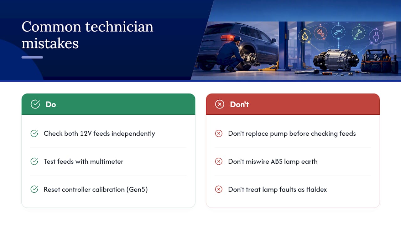
The second recurring trap is miswiring the ABS lamp’s earth during an unrelated repair, which then produces a permanently lit or flickering lamp that has nothing to do with the actual Haldex system. It gets treated as a Haldex fault when it’s really a lighting circuit issue.
Adaptation failing after a mechanically correct pump replacement isn’t random either. It’s almost always a controller that never received the calibration reset it needed, particularly on Generation 5 systems where the internal system fault behaviour documented in workshop reporting shows exactly this pattern.
— Mindaugas
Where to buy OEM Haldex pumps and service kits
A fault code that points squarely at a failed pump only gets solved by fitting a unit built to the correct specification, and that’s precisely where Haldexparts focuses. The Haldex Oil pump 5th generation 9P1906271 Porsche is an OEM-grade replacement built for fifth-generation systems, the exact generation most prone to the internal system fault codes covered earlier in this guide.
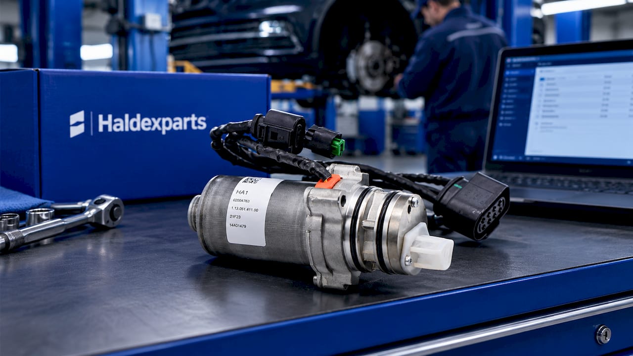
Before ordering, run through a short checklist: confirm the Haldex generation fitted to the vehicle, match the exact part number rather than relying on the vehicle’s build year alone, and check whether the fault history suggests you’ll also need adaptation carried out after fitment. There are suppliers offering pumps, oils, and complete service kits suitable for various AWD platforms, with some providing free shipping on orders above certain thresholds, which can be convenient if you’re fitting a pump alongside a full oil and filter service in the same job. Head to the product page, confirm fitment against your Haldex generation, and get the correct kit ordered before the vehicle comes off the ramp.
Sources
Keep these close at hand for anything beyond a straightforward blink-count read: