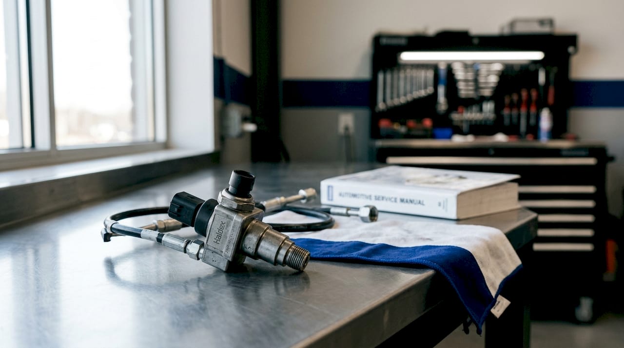
The Haldex pressure sensor is defined as a hydraulic transducer that monitors clutch pack pressure within an all-wheel-drive coupling, converting hydraulic force into an electrical signal the control module uses to manage torque distribution. Without accurate pressure data, the AWD system cannot modulate clutch engagement correctly, leading to traction loss or premature component wear. The sensor sits directly in the hydraulic circuit, reporting real-time pressure to the Haldex control unit, which coordinates with the ABS, ESP, and engine ECU via CAN bus. Understanding the haldex pressure sensor function is the foundation for every diagnostic and maintenance decision on these systems.
How does the Haldex pressure sensor work in an AWD system?
The sensor is positioned in the hydraulic circuit upstream of the clutch pack, where it reads the pressure generated by the electric pump. That pressure reading tells the control module how firmly the clutch is engaged and whether to increase or reduce pump output.
Normal operating pressure sits between 5 and 25 bar under typical driving conditions, with a pressure relief valve threshold at approximately 44 bar. Those numbers matter because any reading outside that band, without a corresponding change in driving demand, points directly to a fault in the sensor, pump, or hydraulic circuit.
The sensor outputs an analogue or digital voltage signal proportional to the measured pressure. The Haldex control module reads that signal continuously and adjusts pump speed to maintain the target clutch clamping force. On earlier generations, this was a purely reactive process: the sensor detected slip, pressure rose, and the clutch engaged. On later generations, the system uses a proactive control strategy that pre-loads the clutch before slip occurs, using predictive data from the ABS and ESP modules.
Generation differences in pressure sensing
Sensor placement and specification vary across Haldex generations:
- 1st and 2nd generation: A dedicated external pressure sensor monitors clutch circuit pressure directly. The sensor is typically rated to 40 bar and is mounted on the pump body.
- 3rd generation: The 40 bar rated sensor remains in use, integrated into the hydraulic circuit before the clutch pack, and is common across Audi, VW, Volvo, and Land Rover platforms.
- 4th generation: Sensor integration becomes tighter with the control module, and CAN bus communication carries pressure data alongside torque and wheel speed signals.
- 5th generation: Some variants infer clutch pressure from pump motor current rather than a dedicated sensor. This is a critical distinction for diagnostics.
Pro Tip: Before condemning a pressure sensor on a 5th generation system, confirm whether the vehicle uses a physical sensor or current-based pressure estimation. Misidentifying the measurement method leads to unnecessary parts replacement.
What types of Haldex pressure sensors exist?
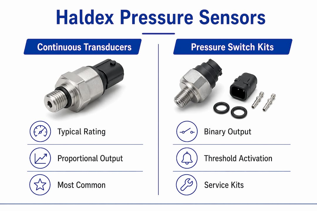
Haldex AWD systems use two broad categories of pressure sensor: continuous transducers and pressure switch kits. Each serves a different role and suits different generations.
| Sensor type | Typical rating | Application | Output type |
|---|---|---|---|
| Continuous transducer | 40 bar | 2nd and 3rd gen AWD | Analogue voltage |
| Integrated transducer | 40 bar | 3rd and 4th gen AWD | Analogue/CAN digital |
| Pressure switch kit | Fixed threshold | Early gen fault detection | On/off signal |
| Current-based estimation | N/A (no sensor) | 5th gen (some variants) | Inferred from pump current |
The continuous transducer is the most common type across automotive Haldex AWD applications. It provides a proportional voltage output across the full pressure range, giving the control module granular data to work with. The pressure switch kit is simpler: it triggers at a set threshold and is used mainly for fault detection rather than active clutch modulation.
Commercial vehicle air brake systems use pressure sensors that carry the Haldex name but are entirely different in function, rating, and installation. Confusing a trailer ABS pressure sensor with an automotive AWD transducer is a diagnostic error that wastes time and risks incorrect repairs. The physical connectors, pressure ratings, and signal protocols are incompatible.
Pro Tip: Always cross-reference the part number against the vehicle’s generation and platform before ordering a replacement sensor. A sensor from a commercial brake catalogue will not function in an automotive AWD coupling, even if the brand name appears similar.
Pressure protection valves in commercial brake circuits also carry pressure-sensing functions, but their safety role in trailer ABS is to protect circuit integrity under high-demand braking, not to modulate clutch engagement. The two applications share a manufacturer heritage but nothing else of practical relevance to AWD diagnostics.
How is the Haldex pressure sensor integrated with vehicle control modules?
The sensor communicates via the vehicle’s CAN bus network, allowing the Haldex control module to react instantly to pressure data and coordinate torque distribution with other systems. This integration is what separates modern AWD from simple mechanical differentials.
The control module receives inputs from several sources simultaneously:
- Pressure sensor: Reports actual hydraulic clutch pressure in real time.
- ABS module: Supplies individual wheel speed data to detect imminent slip.
- ESP module: Provides lateral acceleration and yaw rate data for cornering torque management.
- Engine ECU: Delivers throttle position and torque request data, enabling the system to anticipate traction demand.
The shift to proactive AWD control transformed how pressure sensor data is used. Older reactive systems waited for the sensor to report a pressure drop caused by wheel slip before engaging the clutch. Modern systems use ABS and ESP data to pre-load the clutch hydraulically before slip occurs, so the pressure sensor confirms engagement rather than triggering it. That distinction changes how you interpret a live pressure reading during a test drive.
On 5th generation systems without a physical sensor, the control module estimates pressure from pump motor current draw. High current with low estimated pressure suggests a mechanical restriction. Normal current with low estimated pressure points to pump wear or internal leakage. Technicians working on these systems need to understand that the scan tool pressure figure is a calculated value, not a direct measurement.
The ECU control units for Haldex systems are programmed with pressure thresholds that trigger fault codes when readings fall outside expected ranges. A stored code alone does not confirm sensor failure. The module logs the condition, but the root cause requires live data analysis.
How to diagnose and troubleshoot Haldex pressure sensor issues
Effective diagnosis starts with live data, not fault codes. A fault code tells you a threshold was crossed. Live data tells you when, under what conditions, and whether the pattern matches a sensor fault or a mechanical problem.
Follow this sequence for a structured diagnostic approach:
- Connect a scan tool and access live data. Monitor the pressure sensor output and pump motor current simultaneously. Record baseline readings with the vehicle stationary and the system in standby.
- Perform a controlled test drive. Log pressure and current data across a range of conditions: straight-line acceleration, cornering, and low-speed manoeuvring. Intermittent faults rarely appear on a static test.
- Check pressure at full clutch demand. Command maximum clutch engagement via the scan tool’s actuator test function if available. The pressure reading should rise sharply and hold within the 5–25 bar operating range.
- Cross-check pressure against pump current. Low pressure with normal pump current indicates internal mechanical wear, such as worn clutch plates or failed piston seals, not a sensor fault. Low pressure with low current points to pump failure or an electrical fault.
- Inspect the hydraulic circuit for leaks. A pressure sensor reporting correctly but consistently low values often indicates a leak at a seal or fitting rather than sensor failure.
- Check fluid condition and filter state. Degraded hydraulic fluid and a blocked filter cause pressure drops that mimic sensor faults. Fluid contamination causes clutch plate binding, which produces erratic pressure readings even when the sensor itself is serviceable.
- Verify sensor wiring and connector integrity. Corrosion at the sensor connector produces intermittent voltage signals that the control module logs as pressure faults. Clean and reseat the connector before replacing the sensor.
Pro Tip: Log at least 10 minutes of driving data before drawing conclusions on an intermittent fault. Short static tests miss the thermal and load conditions that trigger pressure sensor failures on worn systems.
Common symptoms of genuine sensor failure include a permanently low pressure reading regardless of pump state, an implausible pressure spike with no corresponding clutch engagement, and a fault code that returns immediately after clearing with no change in driving behaviour. Distinguishing these from Haldex coupling failures caused by mechanical wear requires the cross-checking method described above.
Key takeaways
The Haldex pressure sensor function is to report hydraulic clutch pressure to the control module, and accurate diagnosis requires cross-referencing that reading with pump current, fluid condition, and live driving data.
| Point | Details |
|---|---|
| Pressure operating range | Normal clutch pressure runs 5–25 bar; the relief valve opens at approximately 44 bar. |
| Generation awareness | 5th generation systems may use pump current to estimate pressure rather than a physical sensor. |
| Sensor type selection | Always match the sensor part number to the vehicle generation; commercial brake sensors are incompatible with AWD applications. |
| Diagnostic method | Cross-check pressure readings with pump motor current to separate sensor faults from mechanical clutch failures. |
| Fluid and filter condition | Degraded fluid and a blocked filter produce pressure drops that mimic sensor failure; service these first. |
What I’ve learned diagnosing Haldex pressure faults in the field
The most common mistake I see technicians make is replacing the pressure sensor based on a fault code alone. The code confirms that the control module saw an out-of-range reading. It does not confirm the sensor caused it. I have seen corroded connectors, blocked filters, and worn clutch packs all produce identical fault codes to a failed sensor.
The generation issue catches people out more than anything else. A technician trained on 3rd generation Haldex systems expects a physical sensor and goes looking for one on a 5th generation unit. When they cannot find it, they assume it has been removed or is missing. The reality is that the system never had one. The scan tool pressure figure is calculated from pump current, and that changes everything about how you interpret the data.
The commercial vehicle confusion is less common but more damaging when it happens. A technician sourcing a “Haldex pressure sensor” without specifying the application can end up with a trailer ABS component that shares a brand name but nothing else. Part number verification is not optional on these jobs.
My recommended workflow is always: live data first, fluid and filter inspection second, wiring check third, and sensor replacement last. That sequence catches the majority of faults before you spend money on parts. The Haldex coupling noise guide covers related symptoms that often appear alongside pressure faults, and it is worth reviewing before finalising a diagnosis.
— Mindaugas
Haldexparts: sensors and service kits for AWD maintenance
Keeping a Haldex AWD system in reliable condition requires the right parts matched to the correct generation and platform.
Haldexparts stocks OEM-grade pressure sensor replacements alongside complete Haldex service kits covering oils, filters, and pump components for Audi, VW, Volvo, Ford, and Land Rover applications. Every listing includes generation-specific fitment data, so you select the correct part without guesswork. Orders over £150 qualify for free UK shipping, and the catalogue covers both the sensor components and the hydraulic consumables that directly affect pressure sensor accuracy. Correct fluid and a clean filter are prerequisites for a reliable pressure reading, and Haldexparts supplies both alongside the sensor itself.
FAQ
What does the Haldex pressure sensor do?
The Haldex pressure sensor monitors hydraulic clutch pressure within the AWD coupling and sends that data to the control module, which uses it to regulate torque distribution between the front and rear axles.
What is the normal pressure range for a Haldex AWD system?
Normal operating pressure runs between 5 and 25 bar, with a pressure relief valve set at approximately 44 bar to protect the hydraulic circuit.
How do I know if the pressure sensor has failed or if it is a mechanical fault?
Cross-check the pressure sensor reading against pump motor current. Low pressure with normal current indicates a mechanical fault such as worn clutch plates or a failed seal, not a sensor failure.
Do all Haldex generations use a physical pressure sensor?
No. Some 5th generation Haldex systems do not include a dedicated pressure sensor. The control module estimates clutch pressure from pump motor current draw instead.
Can a commercial vehicle Haldex pressure sensor be used in an automotive AWD system?
No. Commercial vehicle air brake pressure sensors carry the Haldex name but are incompatible in function, rating, and connector type with automotive AWD coupling sensors.